Serial Peripheral Interface (SPI): How It Works, Pins, Modes & Uses
The serial peripheral interface (SPI) is a synchronous communication method used to move data quickly between chips over short distances. SPI is common in microcontrollers, sensors, displays, ADCs, DACs, radio modules, and external flash memory. In a typical SPI connection, one device controls the clock and selects the device it wants to communicate with. Both devices can send data during every clock cycle, making SPI naturally full-duplex. However, SPI does not define a universal command format, packet structure, or maximum clock speed. Those details are specified by the individual devices’ data sheets.
What Is a Serial Peripheral Interface?
Serial Peripheral Interface, usually shortened to SPI, is a short-range synchronous serial bus. A controller – often called a “master” in older documentation – initiates communication, generates the clock signal, and selects the peripheral device involved in the transfer.
A standard SPI connection has four signals:
| SPI signal | Common name | Purpose |
|---|---|---|
| SCK or SCLK | Serial clock | Provides timing for data transfer. |
| MOSI | Controller Out, Peripheral In | Sends commands and data from the controller to the peripheral. |
| MISO | Controller In, Peripheral Out | Sends data from the peripheral back to the controller. |
| CS, SS, or nCS | Chip select | Activates the intended peripheral, typically when low. |
Different manufacturers use different names. A data sheet may refer to MOSI and MISO as SDI/SDO, PICO/POCI, or COPI/CIPO. Always verify the signal direction rather than relying only on the pin name.
How SPI Communication Works
An SPI transfer is a coordinated exchange of bits. The controller pulls the chip-select line low, generates clock pulses on SCK, and sends data on MOSI. At the same time, the selected peripheral can send data back on MISO.
Because SPI is full duplex, each byte written also receives a byte. If the controller wants only to read information, it still sends placeholder data – often 0x00 or 0xFF – to create the clock pulses needed for the peripheral to shift data out.
A common SPI memory-read transaction works like this:
- The controller pulls CS low to select the memory chip.
- It sends a read command and memory address on MOSI.
- It sends dummy bytes to continue generating SCK pulses.
- The memory returns the requested data on MISO.
- The controller pulls CS high to end the transaction.
This sequence is common, but it is not a universal SPI rule. Each peripheral defines its own commands, address format, byte order, and timing requirements.
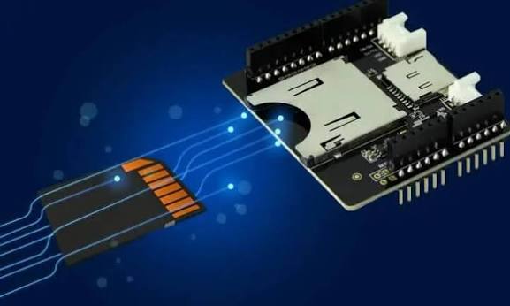
Serial Peripheral Interface Pins Explained
SCK: The Serial Clock
The controller generates the SCK signal. This clock tells both devices when to change and sample data. Unlike asynchronous communication, SPI devices do not need to independently agree on a baud rate because the shared clock controls timing directly.
MOSI and MISO: Separate Data Paths
MOSI carries information from the controller to the peripheral. MISO carries information from the peripheral back to the controller.
When multiple peripherals share an SPI bus, an unselected peripheral should release its MISO output into a high-impedance state. Otherwise, two devices may drive MISO at once, corrupting data and potentially stressing the connected pins.
CS: Chip Select
Most SPI designs use an active-low chip-select signal for each peripheral. SCK, MOSI, and MISO can be shared across the bus, while every peripheral has its own CS line.
Chip select often defines the start and end of a command frame. Some devices require CS to remain low throughout a multi-byte transaction, while others reset their serial state whenever CS returns high. Check the target device’s timing diagram before splitting one command into multiple transfers.
Serial Peripheral Interface Modes: CPOL and CPHA
SPI devices must agree on when data changes and when it is sampled. Two settings define this behavior:
- CPOL (clock polarity): Determines whether SCK is idle low or idle high.
- CPHA (clock phase): Determines whether data is sampled on the first or second clock edge.
Together, they create four SPI modes:
| SPI mode | CPOL | CPHA | SCK idle level | Data sampled on |
|---|---|---|---|---|
| Mode 0 | 0 | 0 | Low | Rising edge |
| Mode 1 | 0 | 1 | Low | Falling edge |
| Mode 2 | 1 | 0 | High | Falling edge |
| Mode 3 | 1 | 1 | High | Rising edge |
Never assume an SPI mode. Match CPOL and CPHA exactly to the peripheral data sheet, then confirm the clock-speed limit, bit order, word size, and chip-select timing.
Connecting Multiple Devices to an SPI Bus
A typical multi-device SPI bus shares the main signals:
- The controller’s SCK connects to every peripheral’s SCK pin.
- The controller’s MOSI connects to every peripheral input.
- All peripheral MISO outputs connect to the controller’s MISO input.
- Each peripheral receives a separate chip-select line.
Only one selected peripheral should drive MISO at any given time. Selecting two devices simultaneously can cause bus contention and invalid readings.
SPI can also use a daisy-chain arrangement, in which data moves through connected devices in series. This can save chip-select pins, but it requires explicit support from every device and adds transfer latency. Separate chip-select lines are usually easier to design and debug.
Advantages of SPI
SPI is popular in embedded systems for several reasons:
- High throughput: Dedicated clock and data lines enable fast, predictable transfers.
- Full-duplex communication: Both endpoints can transfer data during the same clock cycle.
- Simple hardware: A basic SPI link uses few wires and needs no built-in addressing scheme.
- Flexible device protocols: Peripherals can define their own command, address, and data formats.
- Broad hardware support: Most microcontrollers and many sensors, memories, and displays include SPI support.
Limitations of Serial Peripheral Interface
SPI’s flexibility also creates trade-offs:
- More pins for multiple devices: Conventional SPI usually needs one chip-select line per peripheral.
- No single universal standard: Command formats, frame lengths, bit order, and timing vary between devices.
- No built-in acknowledgement or error checking: Firmware must implement retries or integrity checks where needed.
- Short-distance focus: High-speed signals become more sensitive to routing, capacitance, cable length, and poor grounding.
SPI is an excellent choice for communication inside a product or over a short board-to-board connection. It is less suitable for long cables or large networks of devices.
SPI vs. I²C vs. UART
| Feature | SPI | I²C | UART |
|---|---|---|---|
| Timing | Synchronous, controller-generated clock | Synchronous, shared clock | Asynchronous |
| Typical wires | 3–4, plus CS per peripheral | 2 shared wires | 2 data wires, plus ground |
| Duplex | Full duplex | Typically half-duplex | Full duplex |
| Addressing | Usually a dedicated CS per peripheral | Built-in device addressing | Typically point-to-point |
| Best fit | Fast local peripheral links | Many low- or moderate-speed peripherals | Simple device-to-device serial connections |
Choose SPI when speed and deterministic timing matter and the additional chip-select lines are acceptable. Choose I²C when conserving pins and addressing several devices is more important. Choose UART for straightforward asynchronous communication between two endpoints.
Common SPI Applications
Serial Peripheral Interface is widely used for:
- External NOR flash, EEPROM, and SD-card interfaces
- Motion, pressure, temperature, and magnetic sensors
- Small displays and touch controllers
- ADCs, DACs, and digital potentiometers
- Wireless transceivers and Ethernet controllers
- FPGA, DSP, and microcontroller communication
For example, a sensor may use SPI for configuration registers and periodic measurement reads, while external flash memory uses SPI for command, address, and data transactions. The physical bus may look identical, but the protocol above it is device-specific.
SPI Design and Debugging Checklist
Before using an SPI peripheral, confirm the following:
- Voltage compatibility: Ensure both devices use compatible logic levels and share a ground reference.
- Pin mapping: Verify each signal function, especially when datasheet names differ from MOSI and MISO.
- SPI mode: Set the required CPOL and CPHA values.
- Clock speed: Start with a slow clock, then increase it after confirming reliable signals.
- Bit order and frame length: Verify MSB- or LSB-first transfer and the correct word size.
- Chip-select timing: Meet all setup, hold, and transaction-boundary requirements.
- Read clocks: Send dummy bytes when needed to receive data.
- Signal integrity: Keep fast SPI routes short, maintain a clean return path, and address ringing if it appears.
When SPI does not work, inspect CS first, then check the clock mode, byte order, and wiring. Shifted or nearly correct data often indicates the wrong clock edge. All-zero or all-one readings commonly point to chip-select, MISO direction, wiring, power, or logic-level problems.
Conclusion
The serial peripheral interface is a fast, flexible way to connect a controller to nearby chips. Learn the four core signals, match CPOL and CPHA, treat chip select as part of the command frame, and use each peripheral’s data sheet for its exact timing and transaction format. Those fundamentals solve most SPI design and debugging problems.