Wormhole Switching: How It Works, Benefits, and Limits
Wormhole switching is a network flow-control technique that divides a packet into small pieces called flits, or flow-control units. Rather than waiting for an entire packet at every router, the network forwards the header flit as soon as it can select an output link. The remaining flits follow in a pipeline. This approach makes wormhole switching useful for tightly coupled systems where low latency and modest router buffering matter, including multiprocessor interconnects, networks-on-chip, and SpaceWire-based systems. It also involves a key trade-off: one blocked flit can hold resources across several routers.
What Is Wormhole Switching?
Wormhole switching – also called wormhole flow control or, less precisely, wormhole routing – controls when pieces of a packet move through a network. A separate routing algorithm still determines the path to the destination. The name comes from the visual effect of a long packet stretching through a chain of routers: its header may be close to the destination while its later flits remain near the sender.
The key distinction is granularity. Store-and-forward designs buffer a complete packet before forwarding it. Wormhole switching works at the much smaller flit level, so a router needs only a small buffer for each input or virtual channel.
How Wormhole Switching Works
- Split the packet into flits. A packet usually contains a header flit, body flits, and a tail flit. The header carries destination or path information.
- Route the header flit. At each router, the header requests an output channel. If that channel is available, the router forwards it immediately.
- Pipeline the remaining flits. Body flits follow the established route without independently making a routing decision. Multiple links can carry different flits from the same packet at once.
- Apply backpressure when needed. If the header cannot obtain its next output channel, it stops. The stall can propagate upstream through the packet and eventually reach the sender.
- Release resources at the tail. Once the tail flit has passed, the network releases the channel or virtual-channel state for another packet.
A Simple Wormhole Switching Example
Imagine a packet traveling through routers A → B → C → D.
Time 1: A sends Header to B
Time 2: A sends Body-1 to B; B sends Header to C
Time 3: A sends Body-2 to B; B sends Body-1 to C; C sends Header to D
The destination can begin receiving the packet before the sender has transmitted its final flit. By comparison, a store-and-forward router would wait until it had received and buffered the complete packet before forwarding anything to the next hop.
Why Wormhole Switching Reduces Latency and Buffer Cost
Wormhole switching reduces per-hop waiting because it forwards based on the header rather than the complete packet. As the pipeline fills, data transmission occurs across several links at the same time.
It also avoids the need to provide a full-packet buffer at every router. This is especially useful in systems where on-chip memory, power, or silicon area is limited.
Main Benefits of Wormhole Switching
- Low forwarding latency: The header can advance hop by hop before the packet is fully received.
- Small router buffers: Storage is allocated in flit-sized units rather than packet-sized units.
- Efficient pipelining: Packets can stream across multiple network links simultaneously.
- Good fit for structured networks: Meshes, tori, networks-on-chip, and embedded interconnects can use predictable routing rules.
The Trade-Offs: Blocking, Congestion, and Deadlock
Wormhole switching is not automatically faster under every traffic pattern. Its low-buffer design means that a blocked packet can retain channels along much of its route. Other packets needing those channels may be delayed, even if their own next hop is otherwise available.
This creates several challenges:
- Contention: Multiple packet headers may request the same output port.
- Backpressure: A downstream stall can move upstream and reduce packet injection at the source.
- Head-of-line blocking: A packet at the front of a queue can delay packets behind it that may otherwise have been able to proceed.
- Deadlock: Packets can wait in a cycle, with each holding one resource while waiting for another.
For this reason, designers must evaluate traffic patterns and routing dependencies, not just average latency.
Virtual Channels: A Key Deadlock-Avoidance Tool
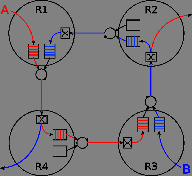
A virtual channel creates multiple independently managed logical channels over one physical link. Each virtual channel has its own state and flit buffer, while the physical link is shared over time.
Virtual channels help in two important ways. First, traffic in one blocked channel does not have to prevent all traffic on the physical link from progressing. Second, designers can assign traffic classes or routing phases to virtual channels so the channel-dependency graph does not form a cycle.
Virtual channels require extra buffer space, control state, arbitration logic, and verification effort. They are a deliberate engineering trade-off rather than a free performance improvement.
Wormhole Switching vs. Store-and-Forward vs. Virtual Cut-Through
| Method | When forwarding starts | Typical buffer requirement | Main implication |
|---|---|---|---|
| Store-and-forward | After the entire packet arrives | Full-packet buffers | Straightforward isolation but additional per-hop latency |
| Virtual cut-through | Before the full packet arrives, when sufficient downstream storage is available | Often packet-scale during blocking | Lower latency but greater buffering needs |
| Wormhole switching | After the header flit obtains the next channel | Flit-scale buffers | Compact and low latency, but stalls may occupy a distributed path |
Where Is Wormhole Switching Used?
Wormhole switching is most relevant in specialized interconnection networks rather than everyday office Ethernet switching.
Common uses include:
- Multicomputers and high-performance interconnects, where processors exchange short, latency-sensitive messages.
- Networks-on-chip, which connect processor cores, memory controllers, and accelerators across a chip or package.
- SpaceWire networks, which are embedded networking systems used in spacecraft and other specialized applications.
Wormhole Switching Design Checklist
Before selecting wormhole switching, consider these questions:
- What is the maximum acceptable latency during congestion?
- Can the routing algorithm guarantee a deadlock-free dependency pattern?
- How many flits and virtual channels can each port buffer within its area and power budget?
- How should the network arbitrate competing traffic: fairly, by priority, or with real-time guarantees?
- What happens when a packet is delayed, corrupted, or lost?
The strongest wormhole-switching designs treat routing, flow control, buffering, and traffic classes as one system.
Conclusion
Wormhole switching enables low-latency packet movement with small router buffers by streaming flits behind a header that establishes the path. It remains important in specialized interconnects, networks-on-chip, and SpaceWire-style embedded networks. Its efficiency comes with a cost: blocking can spread across a route, and poor routing design can create deadlock. Use wormhole switching when routing, arbitration, buffering, and virtual channels can be engineered together.