Rapid Spanning Tree Protocol (RSTP): How It Works, Benefits, and Best Practices
What Is Rapid Spanning Tree Protocol (RSTP)?
Rapid Spanning Tree Protocol (RSTP) is an Ethernet Layer 2 protocol that prevents switching loops while restoring redundant network paths much faster than legacy Spanning Tree Protocol (STP). Originally defined by IEEE 802.1w and later incorporated into IEEE 802.1D, RSTP is a core technology for resilient switched networks.
When two switches have more than one physical path between them, frames can circulate indefinitely unless the network blocks selected links. RSTP builds a loop-free logical topology, keeps redundant paths ready, and can promote a backup path quickly after a failure.
Why Is RSTP Important?
Redundant links improve availability, but they also create the risk of a Layer 2 loop. A loop can cause broadcast storms, duplicate frames, and unstable MAC address tables—often affecting an entire VLAN or campus network.
RSTP solves this by electing one root bridge, selecting the best forwarding paths, and placing unnecessary redundant ports into a non-forwarding state. If the active path fails, RSTP recalculates the topology and activates an eligible alternate path without relying on the lengthy timer-based transitions associated with classic STP.
RSTP vs. Traditional STP
Classic IEEE 802.1D STP relies heavily on timers and moves ports through blocking, listening, learning, and forwarding states. That behavior can make a topology change noticeable to users and applications.
RSTP improves recovery by exchanging BPDUs more actively and using a proposal/agreement handshake on point-to-point switch links. It reduces port states to three and introduces distinct alternate and backup roles, allowing the topology to converge much more quickly when the network changes.
| Capability | Classic STP | RSTP |
|---|---|---|
| IEEE origin | 802.1D | 802.1w, incorporated into later 802.1D |
| Port states | Blocking, listening, learning, forwarding, disabled | Discarding, learning, forwarding |
| Convergence method | Primarily timer-driven | Explicit handshake plus rapid role transitions |
| Redundant-path behavior | Waits through transition timers | Can rapidly promote alternate paths |
| Edge-port behavior | Requires an extension such as PortFast | Native edge-port concept |
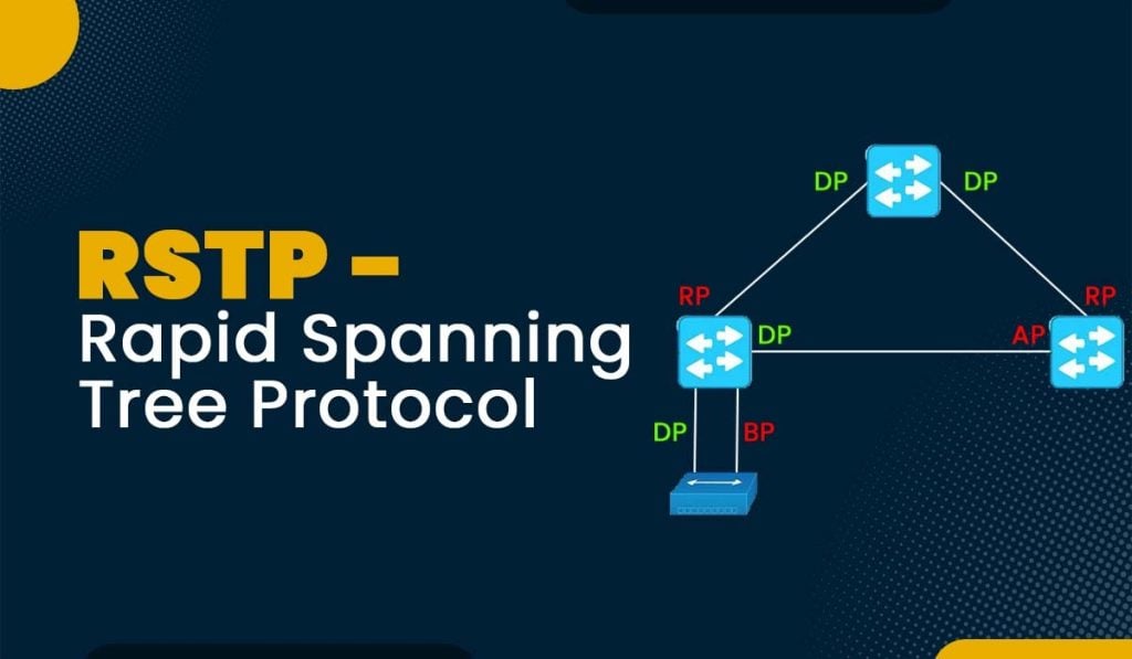
How Rapid Spanning Tree Protocol Works
RSTP follows the same essential objective as STP: choose one loop-free forwarding topology from a physically redundant Layer 2 network.
1. Elect a Root Bridge
All switches exchange Bridge Protocol Data Units, or BPDUs. The switch with the best bridge ID becomes the root bridge. In a well-designed network, administrators intentionally set the root bridge’s priority so the most capable, centrally placed switch wins the election.
2. Assign a Role to Every Port
RSTP determines the best role for each switch port:
| Port role | Purpose |
| Root port | The non-root switch’s best path toward the root bridge. |
| Designated port | The forwarding port for a network segment. |
| Alternate port | A standby path toward the root bridge; it can replace a failed root port quickly. |
| Backup port | A standby path for a segment where another local port is already designated. |
| Disabled port | A port that does not participate in the spanning-tree topology. |
3. Move Ports Through RSTP States
RSTP uses three operational port states:
- Discarding: The port does not forward user traffic or learn MAC addresses. This state covers the legacy blocking, listening, and disabled behaviors.
- Learning: The port learns MAC addresses but does not forward user traffic.
- Forwarding: The port learns MAC addresses and forwards traffic.
4. Use Rapid Convergence When Conditions Allow
On a full-duplex, point-to-point link between switches, a designated port can send a proposal to its neighbor. Once the neighbor has safely synchronized its other ports and responds with an agreement, the link can move to forwarding without waiting through the legacy forward-delay process.
RSTP also treats an interface connected only to an end device as an edge port. An edge port can enter forwarding immediately because it is not expected to create a switching loop. If it receives a BPDU, it stops being treated as an edge port – an important safeguard, but not a replacement for port-security controls.
Rapid Spanning Tree Protocol Link Types
Link type affects how quickly RSTP can transition a port:
- Edge: Connects to an endpoint such as a workstation, printer, or server. It is not intended to connect to a switch.
- Point-to-point: Usually a full-duplex link connecting two switches. This is the preferred condition for rapid proposal/agreement convergence.
- Shared: A shared-medium or half-duplex segment. Rapid convergence is more limited because multiple bridges may share the segment.
Most modern Ethernet switch-to-switch connections operate full duplex, so platforms commonly infer point-to-point status automatically. Confirm the behavior in the platform documentation before overriding link-type detection.
RSTP Configuration Best Practices
- Set the root bridge intentionally. Configure primary and secondary root bridge priorities rather than allowing the election to be accidental.
- Use edge ports only for true endpoints. Never configure an inter-switch, trunk, bridge, or unmanaged-switch-facing interface as edge unless you fully understand the topology.
- Enable BPDU protection on edge ports. Features such as BPDU Guard can disable a port when an unexpected BPDU arrives, preventing an accidental switch connection from creating a loop.
- Treat redundant switch links as point-to-point. Use full-duplex Ethernet and validate that the switch recognizes the appropriate link type.
- Use EtherChannel or LAG for parallel links that should carry traffic together. RSTP sees a link aggregation group as one logical link, avoiding the need to block individual member links.
- Monitor topology changes. Frequent RSTP changes often indicate a flapping interface, an unstable uplink, or an incorrectly connected device.
- Plan interoperability before mixing vendors or STP variants. Vendor terminology and per-VLAN behavior differ. Test boundary links and select a mode appropriate to the environment.
RSTP, Rapid PVST+, and MSTP
RSTP is the standards-based rapid spanning-tree mechanism. Vendors may expose it differently:
- RSTP: Typically one spanning-tree instance for the bridged network or VLAN environment, depending on the platform.
- Rapid PVST+: Cisco’s rapid per-VLAN implementation, which maintains a separate RSTP instance for each VLAN.
- MSTP: Multiple Spanning Tree Protocol groups VLANs into fewer spanning-tree instances, helping large VLAN environments scale while using RSTP-style convergence.
The right choice depends on switch vendor support, VLAN count, operational standards, and interoperability requirements. For a mixed-vendor network, standards-based RSTP or carefully planned MSTP is often simpler than a proprietary per-VLAN approach.
Common RSTP Troubleshooting Checks
When connectivity is interrupted after a topology change, check:
- Which switch is currently the root bridge and whether that matches the design.
- The role and state of each uplink port.
- Whether an endpoint port has received BPDUs or been disabled by BPDU protection.
- Duplex and link-type detection on switch-to-switch links.
- Interface errors, link flaps, and logs showing repeated topology changes.
- VLAN, trunk, or aggregation mismatches that can make the topology behave unexpectedly.
Conclusion
Rapid Spanning Tree Protocol gives Ethernet networks the redundancy they need without leaving users waiting through long Layer 2 recovery periods. By controlling bridge placement, correctly identifying edge and switch links, protecting access ports, and monitoring topology changes, network teams can get the resilience benefits of RSTP while minimizing loop risk.